To display a virtual replica of the dedicated pointer tool, instead of the sphere which only represents the tool's tip, you will:
-
Download the mesh representing the virtual tool and save it to the "Data/MeshModels" directory found under the directory where you installed the tutorial.
-
Determine the transformation between the marker and the tool model:
-
The translational part is determined using the pivot calibration program, just as described in the tutorial. If you don't care whether the shaft of the tool is oriented correctly, you can stop reading here. Note that not calibrating for tool orientation will result in displays in which the tool appears as if it is inside the object even though it is outside. The tip of the tool is still at the correct location.
-
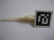
To use the tool orientation you need basic technical knowhow. If you position the marker in a similar manner to that shown in the setup below, you can download this xml file which has the tool orientation. Edit it and add the tool tip location, last three entries in the transformation tag. The first three entries are the quaternion representation of the rotation (x, y, z, s).
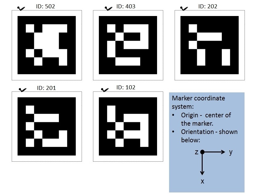
The axes of the printed markers all follow the same convention:
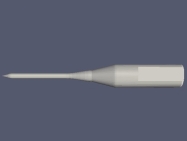
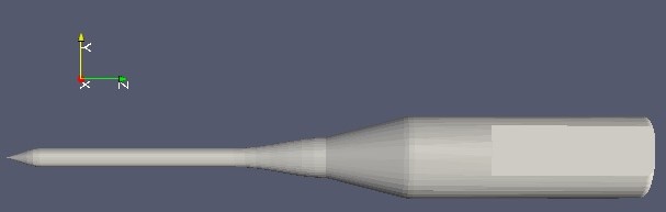
The axes of the virtual tool are known from design:
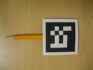
After attaching the marker to our pointer tool we know the orientation of the marker coordinate system:
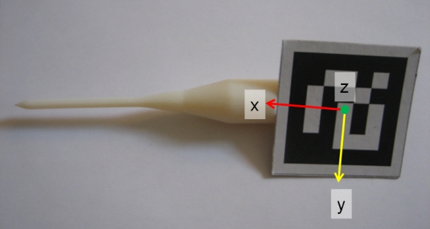
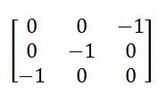
Looking at this specific physical setup we see that the marker x axis maps to the model's -z axis, the marker y axis maps to the model's -y axis and the marker z axis maps to the model's -x axis. Each of these mappings defines the corresponding column in the rotation matrix we thus go from the identity matrix to the following rotation matrix:
If you place the marker at some arbitrary orientation relative to the model you will have to invest some more effort into determining orientation. Note that the marker's x axis always maps to the model's -z axis as you are attaching the marker to the flat region intended for this. Now all that is left to do is determine one more axis. This is left as an exercise (hints: rotate the tool around its long axis or translate the tool along its long axis).